Technically speaking, a breadboard is anything you use to prototype electronics, but normally when we think of breadboards we think of the typical white, plastic, solderless breadboard. If you've never worked with one before, it can take a little time to figure out where all the connections are and how to properly use it. This beginner's guide to breadboards will provide a high-level introduction and cover the basics of how to use one.
Breadboard Rows and Columns
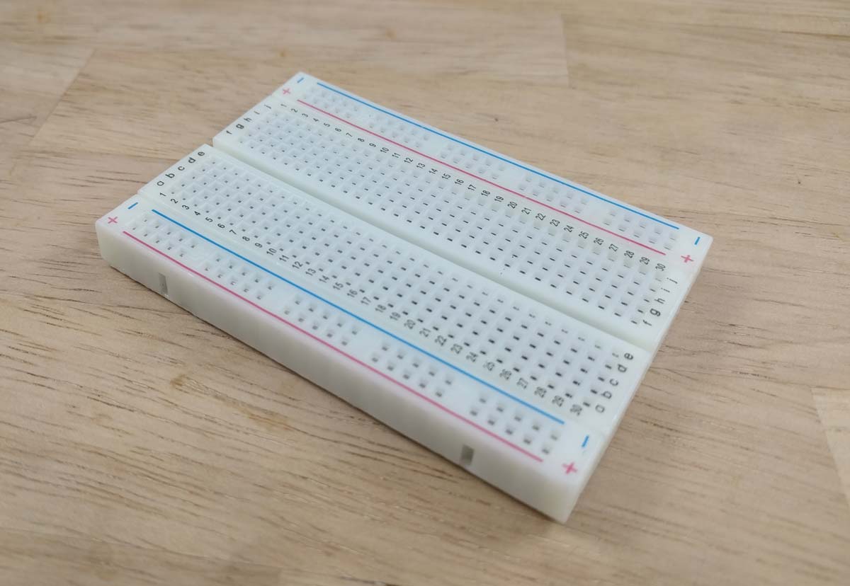
Every breadboard has a similar layout, with rows labeled 1-N and columns labeled a-N. How many rows and columns a breadboard has depends on the specific board. The above image is a typical half breadboard with 30 rows (1-30) and 10 columns (a-j).
All of the terminals on the same row are connected. Columns are not connected. The diagram below shows all of these connections using green lines.
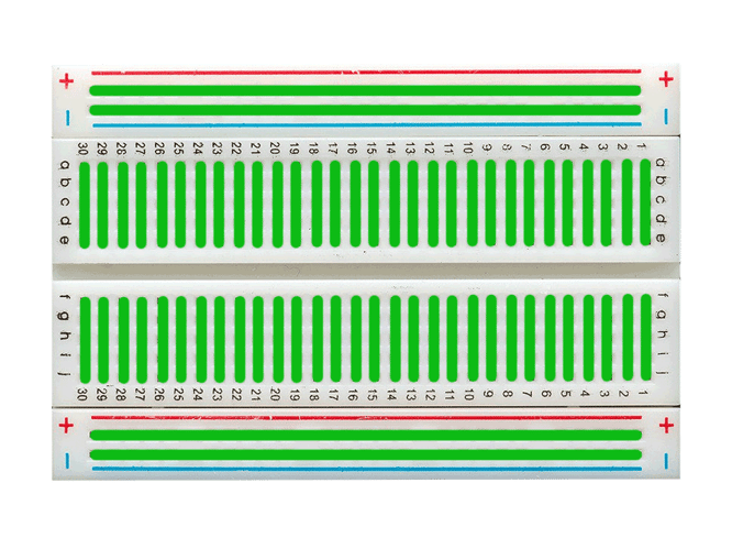 So for example, if you plug things into terminals a27 and d27, they will be connected together.
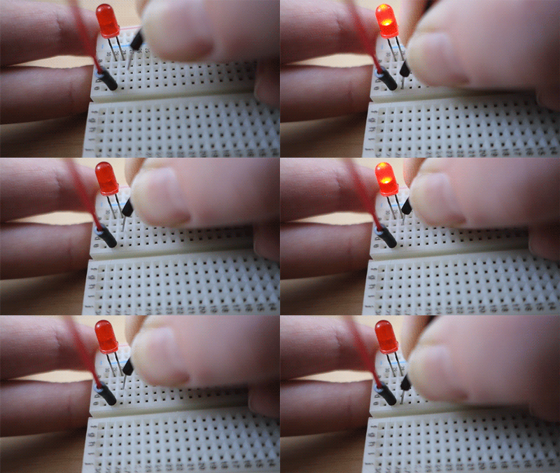
In the animation below, you can see how the LED can be powered by using any of the terminals in the same row.
Negative and Positive Rails
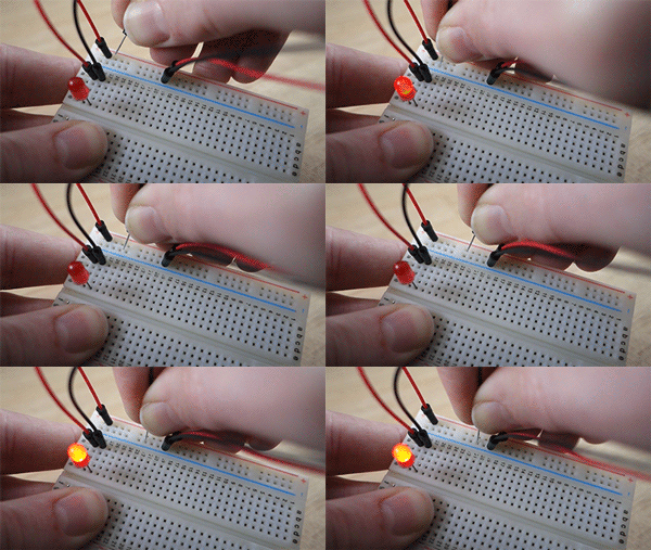
Along each side of a typical breadboard are two sets of negative and positive rails. These exist because it's very common to connect components to power, ground, or both. All terminals along these rails are connected to each other.
The animation below shows how an LED might typically be connected to the rails. Just like above, you can see that any terminal along the rail can be used to complete this simple LED circuit.
The Center Line
Most breadboards also have a center line that separate two sets of columns. This is to allow things like microcontrollers to be plugged in on either side of the center line to expose all of the pins without connecting the pins to each other.
The below image shows how a micrcontroller could be connected to a breadboard and then use its power and ground pins to light up an LED.
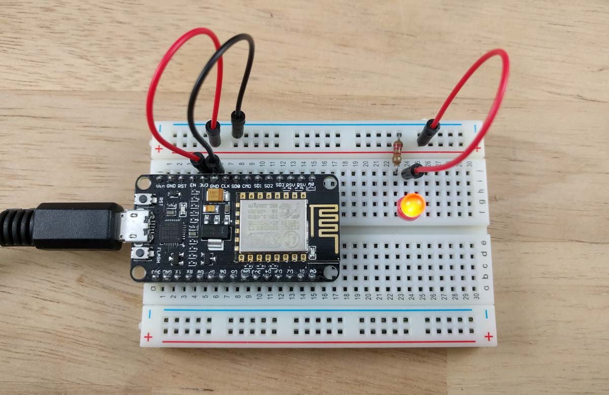
As you can see, the microcontroller is plugged in with its pins on either side of the center line. The power (3V3) and ground (GND) pins on the microcontroller are connected to the positive and negative rails. A resistor then connects the negative lead of the LED to the negative rail. The positive lead is then connected to the positive rail to complete the circuit.
That's it for this overview. You should now have a high-level understanding of breadboard terminals and how they connect to each other. All of our IoT developer kits use half breadboards, which are an easy way to get up and running with building simple circuits.
