In early computing and manufacturing, programmable logic controllers (PLCs) and other industrial equipment were lacking in a standard protocol to communicate to other equipment, internal systems, and external services. Thus, the Modbus protocol was created in 1979 by Modicon (now Schneider Electric). The Modbus protocol was also published to be open-sourced and royalty-free, and has been the primary communication method for PLCs since the '80s.
Modbus was originally designed for serial communication. However, many variants of the protocol exist today to solve different problems. The Modbus TCP/IP or Modbus TCP option enables communication over TCP/IP networks. Modbus TCP allows for machines to be efficiently integrated into Cloud services.
In this article, we will introduce basic terminology and concepts behind the Modbus protocol, and provide an example of bidirectional communication between a Modbus-enabled PLC and the Losant Enterprise IoT Platform.
Modbus Terminology
The Modbus protocol outlines four objects you can read and control on the PLC. Each has a purpose and a particular function.
Coils
Coils represent readable and writable binary outputs (on/off). A simple usage example of a Coil would be connecting an indicator LED to the PLC. You'll need to be able to read what the current status of the LED is (readable) or change the status of the LED (writable).
Discrete Inputs
Discrete Inputs represent readable only binary inputs. Discrete Inputs can be used to read binary sensors like a PIR sensor. Since sensors like the PIR sensor can't be written to, the writable functionality is not needed—Coils exists for that purpose.
Input Registers
Input Registers are readable only, 16-bit analog inputs. Because the protocol supports the transmission of 16 bits of analog data, Input Registers are very flexible and useful for a wide variety of things. A valuable example is reading from analog sensors like the TMP36 temperature sensor.
Holding Registers
Lastly, Holding Registers are readable and writable 16-bit analog inputs and outputs. Holding Registers are primarily used to manage and transmit settings or configuration values between machines and services.
Modbus Functions
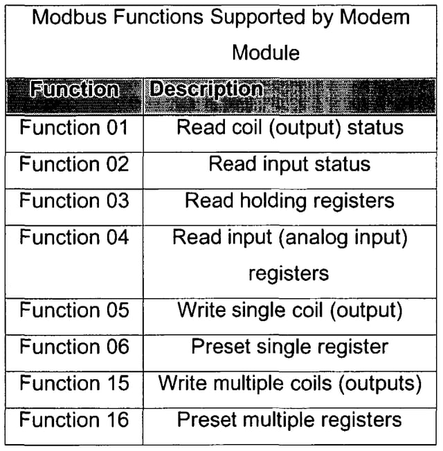
The Modbus protocol also describes a set of functions, which specify how to interact with the entities we described earlier. Instead of walking though each function, here is a helpful diagram:

While these are the most commonly used, there are more functions defined in the protocol. These functions can be invoked by using libraries or tools that implement the Modbus protocol.
Connecting Modbus to the Cloud
Now that we understand the various objects in Modbus and how to invoke change and read values, we can describe a connected implementation of this system. Recall there are many versions of the Modbus protocol. For the rest of this article, any reference to Modbus is referring to the Modbus TCP/IP variant of the protocol.
Due to the flexibility of Modbus, there are many implementations of this solution. The model we suggest introduces another type of hardware called a gateway. Typically, the purpose of the gateway is to aggregate data, translate data between different protocols, and communicate to the Cloud. We can use a gateway and a Modbus-enabled PLC like so:
.png)
As you can see from the diagram above, the PLC (via Modbus) transmits data to the gateway. The gateway will then have the ability to clean up or aggregate the data and send it to Losant using MQTT. MQTT is a lightweight, Pub/Sub messaging protocol typically used to connect hardware to the Cloud.
Once in Losant, a workflow can be set up to enable this data to integrate or trigger third-party services. This process also works in reverse. For example, Losant or a third-party service can communicate to the PLC from the Cloud.
Resources
Here are more resources that will aid in your Modbus cloud solution:
If you want to learn more about connecting Modbus to the cloud with Losant, feel free to contact us.

